
What Is Network Topology Mapping?
Network topology mapping analyzes and discovers all elements or nodes linked to a network in order to visualize and troubleshoot communications. IT Mapping visualizes the physical and logical topologies in a graphical plot, thus simplifying the monitoring of performance and locating faults. It helps to break topologies into smaller, trackable portions, aiding in their navigation which may otherwise be different to understand, due to cabling complexities.
A network topology map contains network diagrams, flowcharts, device inventories, the network’s weak and strong points, and a wealth of additional information about the devices in the network. The IT system mapping scans the network bandwidth and latency, interprets the information gathered, and creates alerts where necessary.
Network topology is the anatomy, arrangement, or layout of telecommunication devices. These devices are represented as nodes, and the topology highlights the relationships between the nodes. Nodes are classed as hardware equipment on your network including both static and mobile devices, switches, and routers.
Editor’s note: Updated the article to add recent network topology market trends, AI-based network topology techniques, and update information for network topology solutions to reflect features and capabilities in 2026.
Network Topology Market and Trends
Key Market Drivers
According to recent market research, several factors are pushing the adoption of network topology tools. One major driver is the growing complexity of modern networks, which makes manual monitoring difficult. The rise of remote work and the expansion of cloud services also increase the need for tools that provide clear visibility into distributed systems.
Another driver is the growing focus on cybersecurity and performance monitoring. Network topology tools help administrators detect issues, visualize connections, and troubleshoot problems faster. Many vendors are also investing in AI and machine learning capabilities to improve automation and analytics within these platforms.
Deployment Models
The market is typically divided into two main deployment models: cloud-based solutions and on-premises solutions.
Cloud-based tools provide flexibility and scalability. They are easier to deploy and often more cost-effective, making them attractive to small and medium enterprises (SMEs). These tools also allow administrators to access network visualizations and monitoring systems from remote locations.
On-premises solutions are commonly used by large enterprises that require greater control over their network infrastructure and data. These organizations often prioritize customization, internal security policies, and direct control of system environments.
Types of Network Topology
Bus Topology
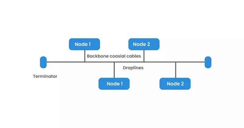
In a bus topology, the computers are all connected to one single cable. Only the addressee accepts and processes the message when one computer sends a signal using the cable. Other computers on the network acknowledge the message, but disregard it.
Bus topology is often used when a network installation is temporary or small in scale. Unidirectional data flow in bus topology makes problem identification tricky, and heavy network traffic slows it down. While the failure of one node does not affect the network, failure of the bus system as a whole will cause the entire network to crash.
A linear bus topology has two endpoints, and a distributed bus topology has more than two endpoints.
Ring Topology
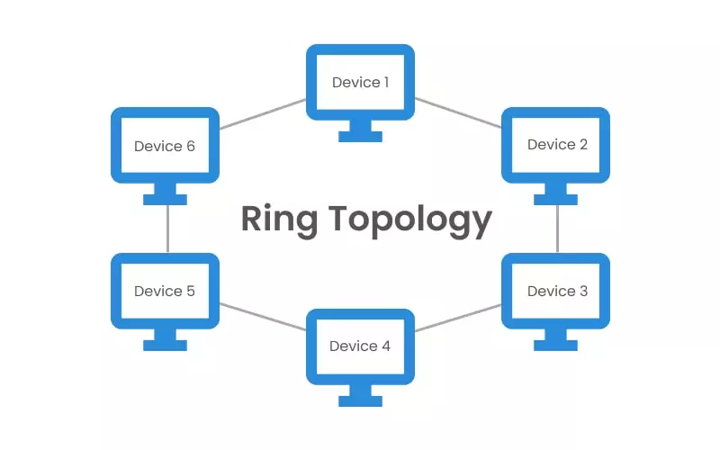
Each computer is connected to the next computer in a circular arrangement; the last connects to the first in order to form a closed loop. Each device serves as a repeater that strengthens the signal received from the previous device.
Read our guide Microsegmentation beginners guide
In a ring topology, messages flow in one direction only, using tokens to pass information from one computer to another. The token is a small packet that is modified with the intended message and the addressee’s details. The token helps each device identify for whom the message is intended. When a piece of information is not intended for a particular computer, the token sends it to the next computer and so on, until it reaches the addressee.
Due to its circular arrangement, ring topology is more complex to troubleshoot than some other topologies, such as the bus topology. Unlike the bus topology, in a ring topology the failure of one computer can affect the entire network, and adding or deleting a device disturbs the network’s performance. In addition, since information has to pass from one computer to another, the network is slower.
Star Topology
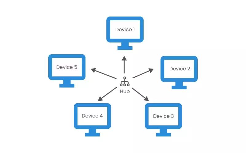
In a star topology, each device is linked to a central controller through its dedicated point-to-point cable. The devices communicate with a central controller that resends the message to the appropriate addressee(s).
This central controller—also called the hub, host, or server—can be active or passive. While an active hub regenerates a signal and sends it to all the computers connected, a passive hub does not regenerate the signal but merely acts as a connection point.
Star topology is easily modified by adding or deleting computers or nodes, and this process does not affect the overall network performance. Hence, a hub with larger ports can be easily installed. However, the failure of the central hub affects the whole network. The central hub can be installed with coaxial cable, optical fiber, or twisted pairs.
Mesh Topology
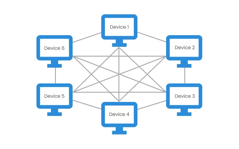
The mesh topology is a robust, fully connected topology used in a WAN, or wide area network. Every device has a dedicated point-to-point link to all other devices, with the result that each computer must have input/output ports. This dedicated P2P link system eases fault identification and isolation, and prevents traffic between computers.
In a mesh topology, data is transmitted through routing and flooding. Routing uses the shortest path between source and destination to transmit data, while flooding sends data from the source to all the network nodes, but only the addressee accepts the data.
Mesh topology can be divided into two subtypes: full mesh and partial mesh. Each device in the workstation is directly connected to the others in the full mesh architecture. On the other hand, in the partial mesh architecture some devices are connected to the nodes with whom they exchange the most data, while others are connected to all nodes. Due to the quantity of required input/output ports and cabling, mesh topology is expensive.
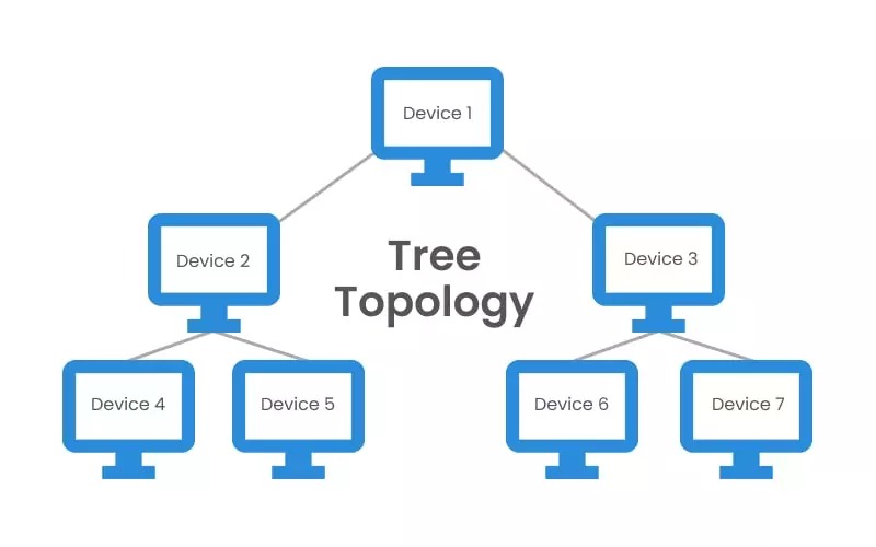
Tree Topology
A bus system connects numerous star topologies in a tree-branch configuration to form the tree topology. A single “hub” node at the top of the network is connected to several lower-level nodes via point-to-point links. Additionally, these lower-level nodes are linked to one or more nodes (downlines) in the following level. The “branching factor” of the tree is the fixed number of nodes connected downline.
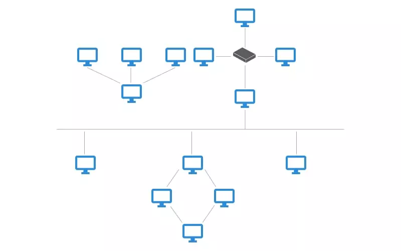
Hybrid Topology
Hybrid topology occurs when two or more types of topologies are connected. In a single establishment, one department of an establishment might be using a ring topology, while another department opted for a bus topology. These two networks can connect to a star topology’s central hub. However, the architecture of the resulting arrangement does not exhibit any standard network topologies. Hybrid topology’s robust architecture often makes it costly, since it requires extensive infrastructure, cooling, and cabling.
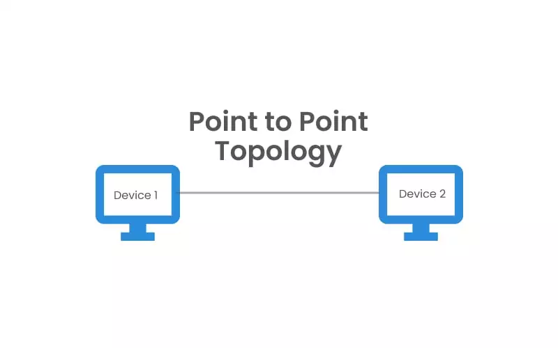
Point-to-Point Topology
Also referred to as P2P, point-to-point is the most basic network topology and consists of a direct connection between two computers and peripheral devices. The communication medium is monopolized in this topology since it is not shared, and there is no need for a device identification mechanism.
Daisy Topology
A daisy topology can come in linear or ring forms. Like in a ring topology, when a computer sends a message, each computer bounces the message in the chain until it reaches its destination. However, whereas the ring topology closes up through a circle of connections (see Figure 1,) a daisy topology has an endpoint that makes it easy to add new devices and nodes to the network (see Figure 3.) This topology is also known as chain topology because it connects the network devices in a sequence.
Why Perform Network Topology Mapping?
Network mapping provides administrators with crucial performance insights, such as device status, physical connections, and traffic metrics, so that administrators can fix issues faster, thus maximizing uptime. With mapping, a potentially devastating issue can be managed before problems occur. For example, if there is a security breach on any of the devices in the network, mapping solutions will indicate a change in the traffic and data flow, signaling to the administrator that there is an issue before that issue is encountered by any network user.
Prompt responses to network and device faults are essential to the growth of any telecommunications organization, and quick detection of these faults and their root cause is the crux of network topology mapping. Network topology mapping, therefore, improves disaster planning and enhances network control and protection.
Network Topology Mapping Techniques
There are three main network topology mapping techniques: SNMP, active probing, and route analytics software.
SNMP
SNMP is an acronym for Simple Network Management Protocol. It is an Internet Standard mapping technique that scans network devices automatically and exposes technical data as variables on the managed systems. In order to describe the system status and configuration, these variables are then organized in a management information base (MIB.)
The SNMP application layer (OSI Layer 7) can also access and change the system variables on the network devices. Furthermore, SNMP gathers the information discovered, including the number of active ports and temperature value, and uses them to create objects in the network map. There are three versions of SNMP (SNMPv1, SNMPv2, and SNMPv3,) with SNMPv2 being the most frequently deployed protocol version.
Active Probing
Active Probing is a technique that diagnoses networks by sending probe packets into the network to gather information. It then uses the data retrieved from the system’s logical topology architecture (called the traceroute-like methods) or its IP to create a network map. Active probing relies on the data plane of the network and its router adjacencies to map its topology. One advantage of active probing is its exactitude, because the paths returned by probes are the forwarding path that data takes through the network.
Route Analytics Software
Route analytics software is an automated mapping technique that explores the topology of a network using Layer 2 and Layer 3 information to map and discover devices connected to the system. For clarity, Layer 2 is the data link packet of a network system, while Layer 3 gathers the IP addresses of the network infrastructures.
While SNMP observes only the system interfaces and links, route analytics software explores the network further by providing complete routing history, traffic monitoring, end-to-end statistics, and detailed performance diagnostics.
AIOps
AIOps (Artificial Intelligence for IT Operations) applies machine learning and data analytics to automate and enhance network topology mapping. It ingests data from multiple sources such as logs, metrics, and topology maps, then analyzes patterns to identify anomalies, dependencies, and potential failures. Unlike traditional techniques, AIOps can correlate events across the network, helping teams detect root causes faster and reduce noise from unrelated alerts.
In topology mapping, AIOps improves accuracy and efficiency by continuously learning from network behavior. It can predict capacity issues, recommend optimizations, and automatically update topology views as the environment changes. This is especially useful in dynamic environments such as cloud and hybrid networks, where manual mapping quickly becomes outdated. By combining automation with predictive insights, AIOps helps teams move from reactive troubleshooting to proactive network management.
Key Features of Network Topology Mapping Tools
Network topology mapping tools offer several key features that help IT teams visualize, monitor, and optimize their network infrastructure. These features ensure efficient management, troubleshooting, and security of the network.
- Automated Discovery: Automated discovery scans the entire network to identify and map all connected devices, reducing manual effort. This feature ensures that network diagrams remain up to date even as the network evolves.
- Real-Time Monitoring: Real-time monitoring provides continuous oversight of network health and performance. It tracks changes in topology, device status, and traffic flow, alerting administrators to potential issues before they cause disruptions.
- Layered Mapping: Some tools offer multi-layered mapping, which enables users to view physical, logical, and application-layer connections separately. This improves network visibility and helps diagnose issues more effectively.
- Customizable Visualization: Interactive and customizable network diagrams allow IT teams to organize views based on hierarchy, connectivity, or device roles. Many tools also offer zooming, filtering, and color-coded indicators for better clarity.
- Integration With IT Management Systems: Modern topology mapping tools integrate with security information and event management (SIEM), IT asset management (ITAM), and network monitoring solutions. This integration helps correlate network topology with security threats and performance metrics.
- Historical Data and Change Tracking: Many tools log past network configurations, enabling teams to compare current and historical topologies. This feature helps identify trends, troubleshoot recurring problems, and plan for network expansions.
- Security and Compliance Insights: By mapping all devices and connections, topology mapping tools help identify unauthorized devices, misconfigurations, and compliance violations. Some tools also include security analytics to detect anomalies and vulnerabilities.
- Automated Alerts and Reporting: Advanced tools provide automated alerts when devices go offline, bandwidth thresholds are exceeded, or security issues arise. They also generate reports on network performance, usage trends, and risk assessments.
7 Notable Network Topology Mapping Tools
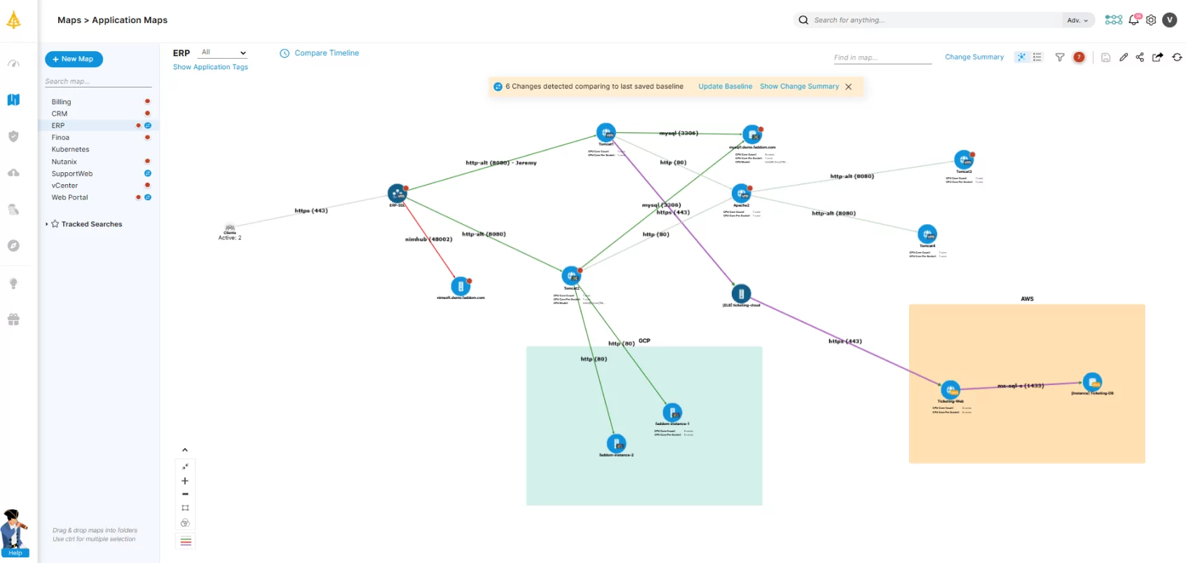
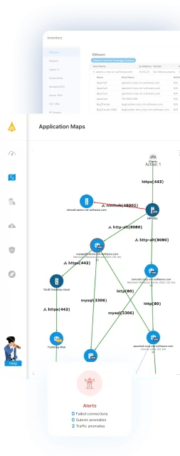
1. Faddom
Faddom is an agentless network topology mapping platform that automatically maps both cloud and on-premises networks, regardless of the topology type, in under an hour. It provides IT teams with real-time visibility into their entire infrastructure, enabling them to optimize performance, troubleshoot issues faster, and enhance security.
Key features include:
- Agentless and passive application mapping: Automatically detects and visualizes dependencies without requiring agents.
- Scalability: Adapts to organizations of any size, from small IT teams to large enterprises.
- Security-focused design: Operates without active network scanning, reducing security risks.
- Hybrid environment support: Maps dependencies across on-premise, cloud, and hybrid infrastructures.
- Change impact analysis: Helps IT teams assess the risks of infrastructure modifications before implementation.
- Seamless Integrations: Connects with ITSM and SIEM tools like ServiceNow for enhanced management.
Learn more about Faddom for application mapping or take the next step and book a demo with our experts!
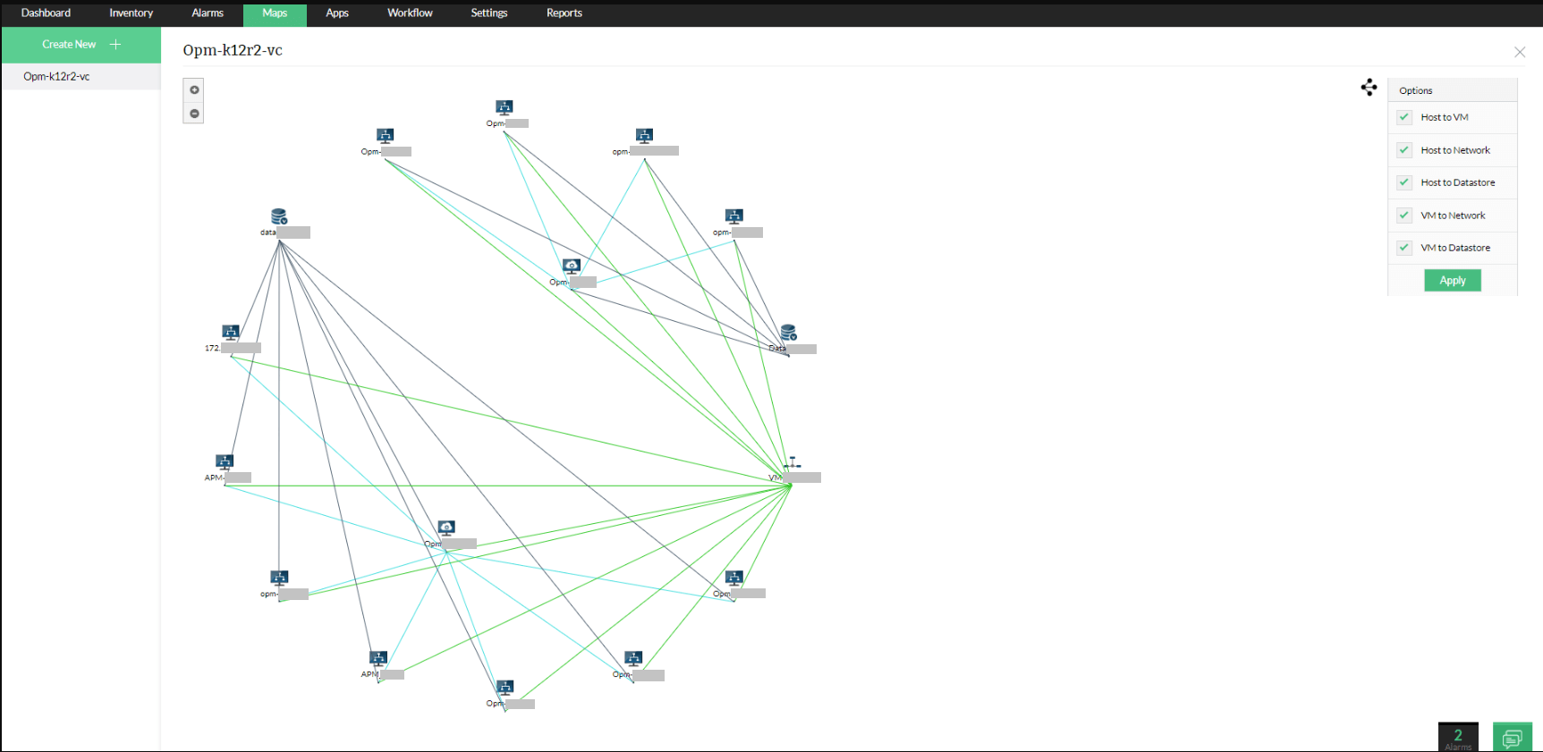
2. OpManager Network Mapping

OpManager provides network mapping as part of its broader network monitoring platform, enabling automatic discovery and visualization of devices and their relationships. It builds dynamic topology maps that reflect both physical connections and logical dependencies, helping teams understand how infrastructure components interact and identify issues more quickly.
Key features include:
- Automated device discovery: Identifies and classifies devices using protocols such as SNMP, ICMP, and WMI.
- Dynamic topology visualization: Creates interactive maps that reflect real-time network connectivity and performance.
- Layer 2 mapping: Displays physical connections between switches, routers, and endpoints.
- Dependency mapping: Shows relationships between devices and services to support root cause analysis.
- Topology-aware alerting: Correlates alerts with network structure to reduce noise and highlight the actual source of issues.
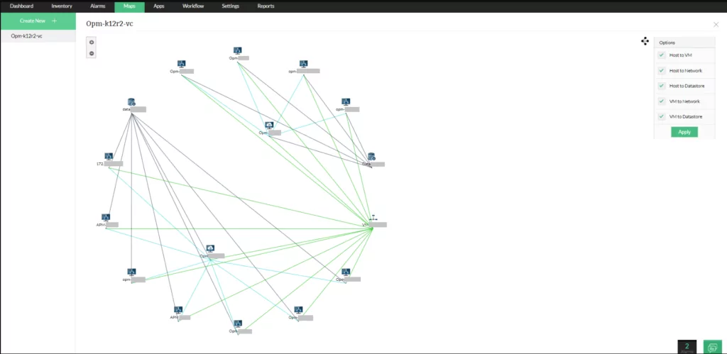
Source: ManageEngine
3. N‑able N-central Network Mapping


N-able N-central includes built-in network mapping capabilities designed for managed service providers and IT teams managing distributed environments. It automatically discovers devices and generates topology maps, allowing teams to maintain visibility and troubleshoot issues without manual documentation.
Key features include:
- Automated network discovery: Detects devices and updates topology maps as changes occur.
- Dynamic topology visualization: Creates detailed visual representations of network layouts and connections.
- Scheduled scanning: Performs regular scans to keep maps aligned with current network configurations.
- Centralized dashboard: Provides a single interface for monitoring and managing network maps.
- Troubleshooting support: Helps quickly identify performance issues using up-to-date visual layouts.
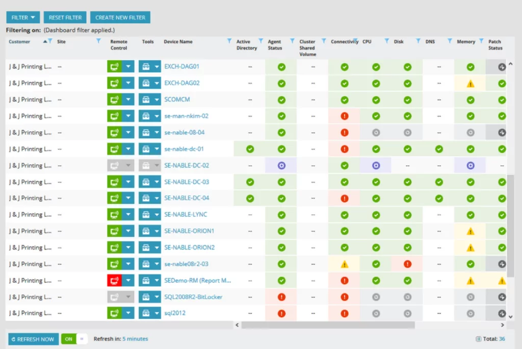
Source: N‑able
4. SolarWinds Network Topology Mapper

SolarWinds Network Topology Mapper is a dedicated tool for automatically discovering network devices and generating topology diagrams. It supports multi-level mapping and integrates various discovery protocols to maintain accurate and up-to-date representations of network environments.
Key features include:
- Automated topology discovery: Uses protocols such as SNMP, ICMP, WMI, and CDP to map network devices.
- Dynamic diagram generation: Automatically creates and updates network maps as the environment changes.
- Multi-level mapping: Supports both logical and detailed topology views for complex environments.
- Topology change detection: Identifies new or modified devices to keep maps current.
- Manual editing options: Allows customization of maps and device relationships when needed.
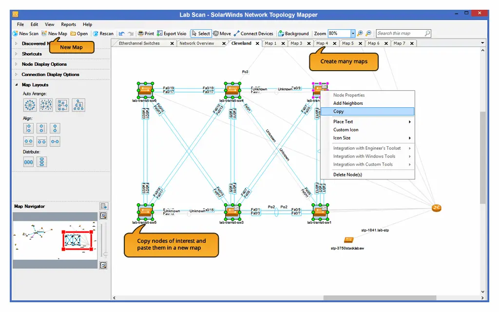
Source: SolarWinds
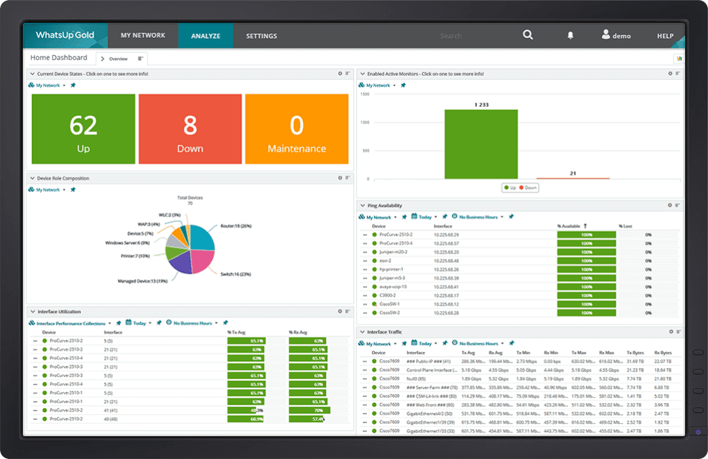
5. WhatsUp Gold’s Network Mapping

WhatsUp Gold provides integrated network mapping alongside monitoring capabilities, using Layer 2 and Layer 3 discovery to build interactive topology maps. It combines mapping with performance data to help teams visualize connectivity, dependencies, and network health in real time.
Key features include:
- Layer 2 and Layer 3 discovery: Maps devices and their connections using multiple discovery techniques.
- Automatic map generation: Builds interactive topology maps that update as network changes occur.
- Dependency mapping: Identifies downstream relationships to improve fault isolation and alert handling.
- Traffic visualization: Displays bandwidth usage and link status with visual indicators such as heat maps.
- Customizable maps: Allows users to tailor layouts with annotations, images, and logical groupings.
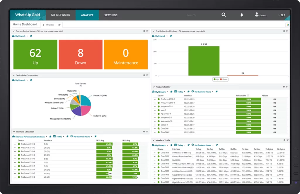
Source: WhatsUp Gold
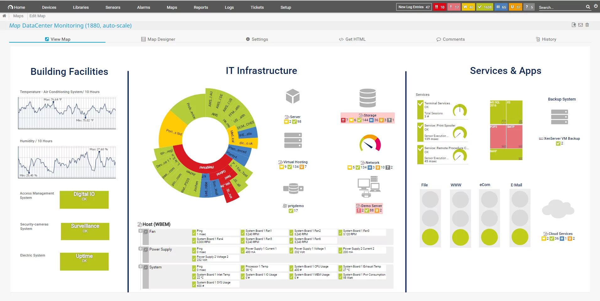
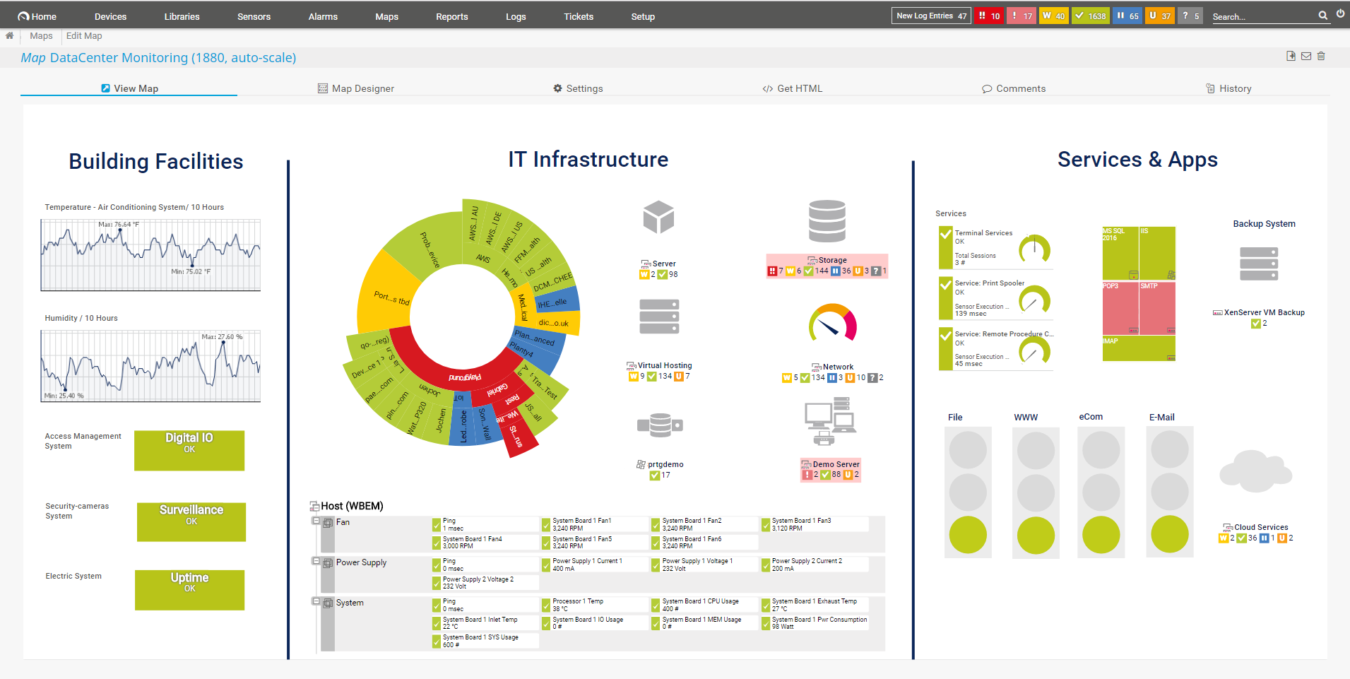
6. Paessler PRTG Network Monitor

PRTG Network Monitor includes network mapping capabilities within its broader monitoring platform, combining automatic discovery with continuous performance tracking. It provides visibility into devices, traffic, and system health through a centralized interface.
Key features include:
- Automatic network discovery: Detects devices and configures monitoring using predefined templates.
- 24/7 monitoring: Tracks bandwidth, device health, and network performance continuously.
- Preconfigured sensors: Monitors various devices and metrics using built-in sensor types.
- Centralized monitoring console: Provides a single view of the entire network environment.
- Alerting system: Sends notifications when thresholds or performance issues are detected.
Source: Paessler
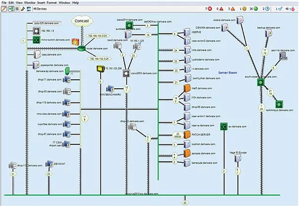
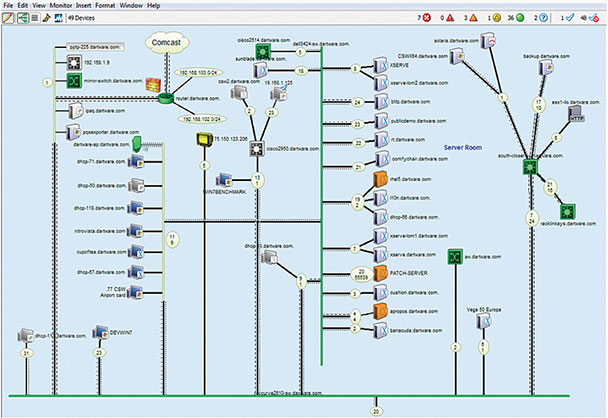
7. Intermapper
![]()
Intermapper is a network monitoring and mapping tool that provides real-time visualization of network devices and their status. It focuses on combining interactive maps with monitoring data to help teams quickly detect and resolve issues across distributed environments.
Key features include:
- Automatic network mapping: Discovers and maps all IP-enabled devices in the network.
- Real-time visualization: Displays network status using color-coded indicators for quick assessment.
- Proactive alerting: Notifies teams when performance thresholds are exceeded.
- Cross-platform management: Supports monitoring and management across multiple operating systems.
- Historical reporting and capacity planning: Uses collected data to analyze trends and plan network growth.

Source: Intermapper
Conclusion
Network topology mapping is essential for maintaining efficient, secure, and scalable IT infrastructure. Organizations can optimize performance, quickly detect issues, and strengthen security by visualizing network components and their relationships. Automated tools simplify this process, ensuring accurate and up-to-date topology maps that support informed decision-making and effective network management.


